


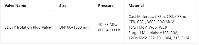
 The above are pressure and caliber dimensions, which are designed according to standards or user requirements
Forging and casting materials can be provided according to user needs, and the selection of valve body and internal material is determined based on the usage conditions of pressure and temperature
User Manual for Hydraulic Test Blocking Valve
1. Purpose
This valve is used on the reheater and main steam pipeline of the 25MW-1000MW unit boiler as an isolation device for the segmented water pressure test of the boiler. After the hydrostatic test is completed, remove the internal components such as the flat blocking plate and support plate, and install them into the guide sleeve, which becomes the pipeline. It has the advantages of low resistance, uniform stress distribution, and extended service life.
2. Structural characteristics
2.1 The valve cover adopts a self sealing structure, which is reliable in sealing, and the higher the pressure, the better the sealing.
2.2 The valve body branch pipe is basically equivalent to the inner diameter of the pipeline. After removing the internal components such as the flat blocking plate and support plate, the guide sleeve is installed, and the valve is equivalent to a section of pipeline with low pressure loss.
During the hydrostatic test, the flat blocking plate and support plate are sealed with "O" - shaped soft rings, and the valve cover is sealed with a self sealing ring, ensuring safe and reliable sealing with good performance.
2.4 All internal components are installed from the top, without the need to cut the valve body, making maintenance and repair convenient.
The 2.5 valve design has the advantages of economy, labor saving, and convenience. The internal components can be removed after water pressure, and can be reused multiple times. It has the advantages of reducing costs, reducing labor intensity for workers, and saving users' operation time.
3. Installation and storage
3.1 Installation and Welding
When welding the valve body and pipeline, it is necessary to strictly follow the welding specifications and welding processes provided by the manufacturer.
3.1.2 Use lifting eye screws to lift the valve, and select the threaded part into the valve body.
Attention: The four in one ring must be installed into the valve body groove to prevent the valve cover from rising and causing leakage at the self sealing point due to improper installation.
The flow arrow shown on the valve body indicates the direction of steam medium flow.
Special attention: The water pressure test medium at the inlet of the reheater and the steam running cut-off flow direction are opposite, while the water pressure test medium at the outlet of the reheater and the main steam blocking valve flow in the same direction as the steam running medium.
Before installation, the valve inlet pipeline and all connecting parts should be thoroughly cleaned. The surrounding environment of the valve must eliminate any artificial, harmful gases, foreign substances suspended in the air, or any adverse external conditions that may affect the normal operation of the valve.
3.1.5 Check the sealing surfaces on the flat blocking plate and the valve body to ensure that the surfaces are undamaged and clean; Check the O-ring to ensure it is intact, seamless, and not aging.
3.2 Storage
3.2.1 Valves must be stored in dry and non outdoor conditions.
3.2.2 Valves must be loaded, unloaded, and transported by hand or using suitable lifting equipment to prevent damage.
4 Maintenance and Repair
4.1 Daily Maintenance
4.1.1 Check whether the self sealing structure of the valve leaks.
4.1.2 Check whether the valve surroundings are kept clean and free of debris.
4.2 Disassembly and Assembly
4.2.1 Disassembly
(1) Before disassembling the valve, ensure that the shut-off valve has been completely discharged from the pipeline and valve body cavity.
(2) Loosen the nuts on the cover plate, tighten the lifting ring screws on the cover plate, and remove the cover plate and bolts.
(3) Tap the valve cover with a heavy hammer to loosen it.
(4) Remove the four in one ring, pressure ring, and sealing ring, and pay attention to protecting the sealing ring when lifting it out.
(5) Loosen the adjusting nut on the support plate.
(6) Lift out the flat blocking plate, support plate, and adjusting nut and other components.
4.2.2 Assembly
(1) Check if all parts are intact and undamaged. All parts should be thoroughly cleaned, and the cleaned valve components should be free of oil stains and rust spots. The valve components should meet relevant technical requirements.
(2) Install flat blocking plates, support plates, and adjusting nuts.
(3) Tighten the screw of the adjusting nut.
(4) Install the four in one ring, pressure ring, and sealing ring.
(5) Install the bolts on the cover plate and tighten the nuts on the cover plate to pre tighten the sealing ring.
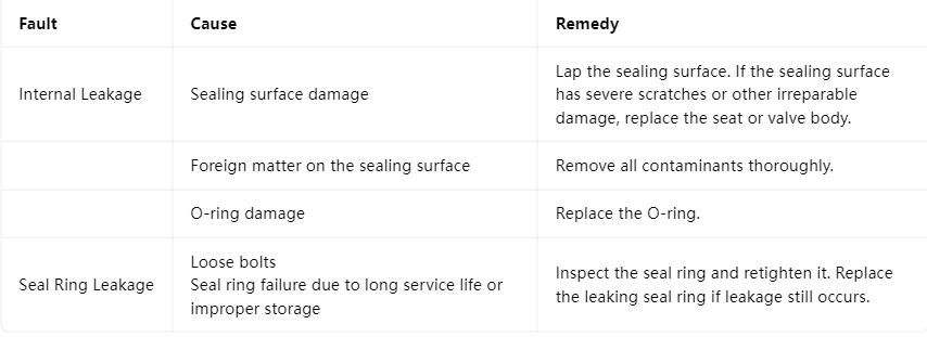
4.3 Fault Handlin
主要外形图:

